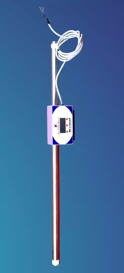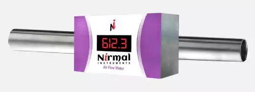


The flow meter clamps onto a pipe, with two flow sensing probes projecting into the pipes through 5mm. drilled holes. It seals directly to the pipe; no cutting or welding is required for installation. Because each flow meters is made and calibrated fora specific size of pipe, the display indicates flow directly, with no setup or adjustments.
The meter measures flow by maintaining one probe warmer than the other. It calculates the mass velocity from the amount of heat required, and then calculates the flow on the basis of pipe area. The flow rate in scfm is shown on a larger 4 digit display 485 output and pulse output permit remote display, totalizing and data collection.
| TECHNICAL SPECIFICATIONS | |||
| Accuracy | 2 percent of reading plus one percent of full scale at air temperatures between 4 and 50 Degree Celsius | ||
| Fluids | Compressed air and Nitrogen Gas | ||
| Operating Pressure | 200 psig maximum | ||
| Input Power | 200mA at Ls to 24VDC | ||
| Ring Material | Aluminum | ||
| Display | Four-digit LED display | ||
| Data Options | 1. RS 485 Interface and software kit 2. Pulse output without Display 3. Optional Windows TAB local Display with Software |
||
Ranges and Scaling :
Displays are available in scfm, Nm3/min and Nm3/hr. The published scale range of each meter is its calibrated range, the meter will continue to function, at reduced accuracy, at higher and lower flow rates. The milliamp output increases linearly from four milliamps at zero flow to 20 milliamps at a pre-determined flow rate that is displayed fora few seconds as the meter starts up. The pulse output produces five pulses for each standard cubic foot of air in all meter sizes.
| Ref. No. | Pipe Size | Measuring Range |
| 4001 | 1/2 Inch | 1 - 90 |
| 4002 | 3/4 Inch | 1 - 120 |
| 4003 | 1 Inch | 2 - 140 |
| 4004 | 1.25 Inch | 2 - 150 |
| 4005 | 1.5 Inch | 2 - 200 |
| 4006 | 2 Inch | 3 - 350 |
| 4007 | 3 Inch | 7 - 700 |
| 4008 | 4 Inch | 15 - 1500 |
| 4009 | 5 Inch | 20 - 2500 |
| 4010 | 6 Inch | 30 - 3000 |
| 4011 | 8 Inch | 30 - 4500 |
| 4012 | 9 Inch | 30 - 6860 |
| 4013 | 10 Inch | 30 - 14000 |
| 4014 | 11 Inch | 30 - 16940 |
| 4015 | 12 Inch | 30 - 20160 |
| 4016 | 13 Inch | 40 - 23660 |
| 4017 | 14 Inch | 40 - 27440 |
| 4018 | 15 Inch | 40 - 31500 |
| 4019 | 16 Inch | 40 - 35840 |
| 4020 | 17 Inch | 50 - 40460 |
| 4021 | 18 Inch | 50 - 45360 |
| 4022 | 20 Inch | 50 - 56000 |
Calibration Adjustment :
Table indicates the stock ring sizes and it indicates the types of pipe on which meters are normally calibrated. Calibrations are also performed on some thinner-walled pipes in the same outside diameters. For other pipe types and wall thicknesses, an adjustment will be made to the calibration for small differences in inside area. This is commonly done for British or DN pipe sizes.
Meter output varies by about two percent per 100 psi. Standard calibrations are for 100 prig; adjustments can be provided for applications at substantially higher or lower pressures; they are not needed for most compressed-air applications.
Power Supply :
The meter requires 24 Volt +/- 15 percent dc power and it draws approximately 250 mA. Surge suppression is provided to protect the meter against spikes that may occur in industrial dc power systems.
Applications :
The meter is designed for use with compressed air and nitrogen Gas. The Meter works much better on Low level air consumption, which helps the customer to identify the exact air leakages and save the energy cost. Meters can be installed in multiple meter network to complicated networks or even a single meter environment, Kalki Vayu Software system will support the complete air consumption information system.